QUADRANT SYSTEM
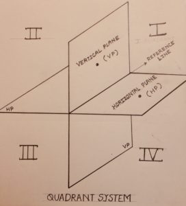
The entire space is divided into four rooms named as first quadrant, second quadrant, third quadrant and fourth quadrant respectively following an anticlockwise pattern. The division of the space is done by two planes commonly known as vertical plane (frontal plane) and horizontal plane bisecting each other. The line of intersection of these two planes is called reference line or XY line.
Diagram
The observer is assumed to be viewing the object from the right-hand side of the quadrant system. His position being unaltered with respect to the object being placed in all the four different quadrants. In brief it can be concluded that the objects can be placed in any of the four quadrants, but the observer is always on the right-hand side of the quadrant system for getting the front views.
Also, when the plane of projection comes between the observer and the object as in the second and the third quadrant then the plane is assumed to be transparent.
Universally, to obtain the 2D drawings of an object the horizontal plane is rotated clockwise.
Diagram
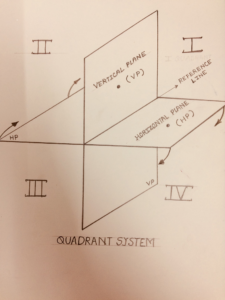
When the Horizontal plane is rotated clockwise by 90 degrees about the reference line it is observed that for the second and the fourth quadrant, the vertical and the horizontal plane overlap with each other, at the same time even the two views individually obtained on each plane will be overwritten on each other which will lack clarity in understanding the drawing. Hence the first and the third quadrant is preferably chosen for projection named as First angle projection and Third angle projection respectively.